GENEPROJ · Engineering guides
2D Drawings and 3D CAD for Transformers
Work with both the geometric construction of a component and its technical representations. Geneproj combines parameter-driven models, a programmable 2D drawing editor and a 3D CAD environment for component development.
Practical application
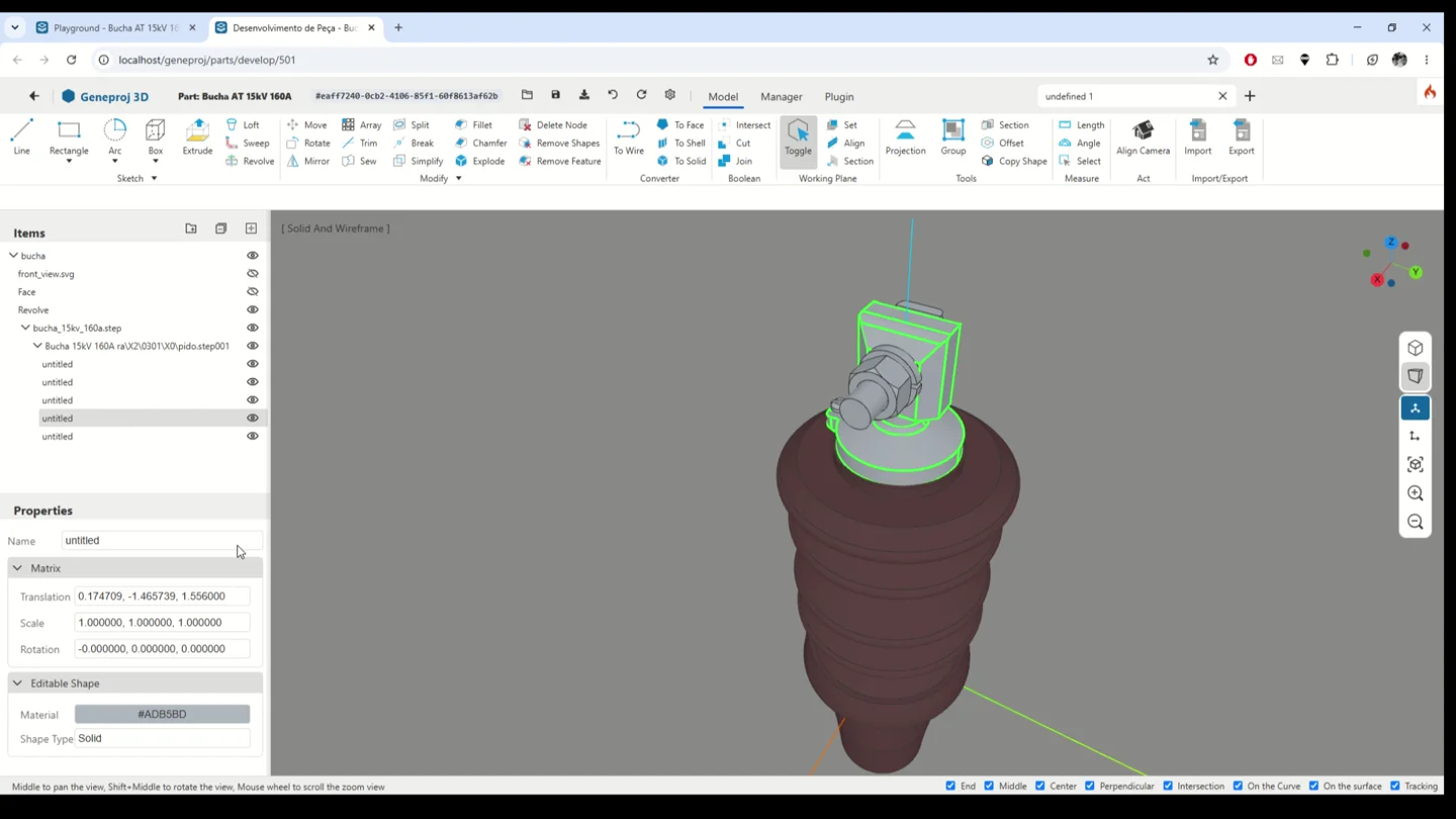
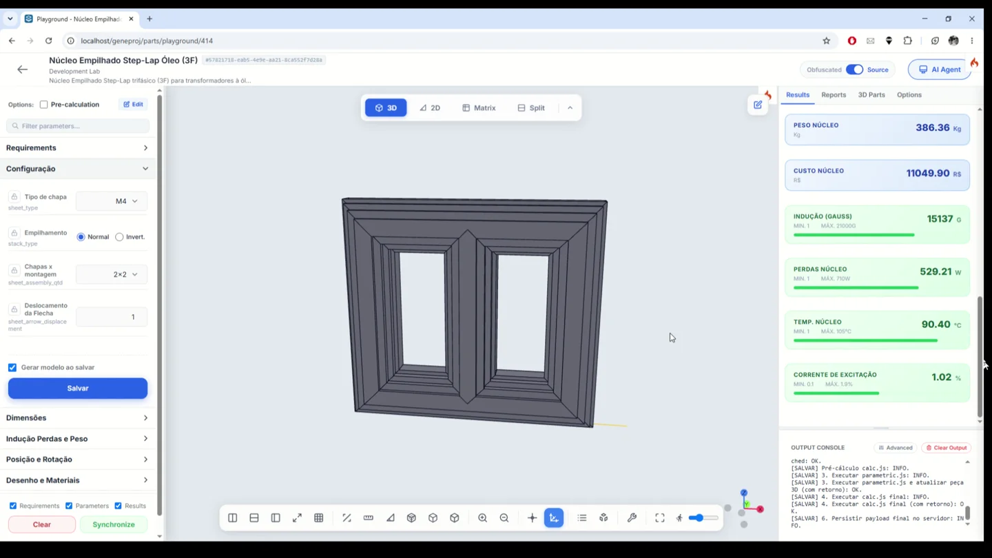
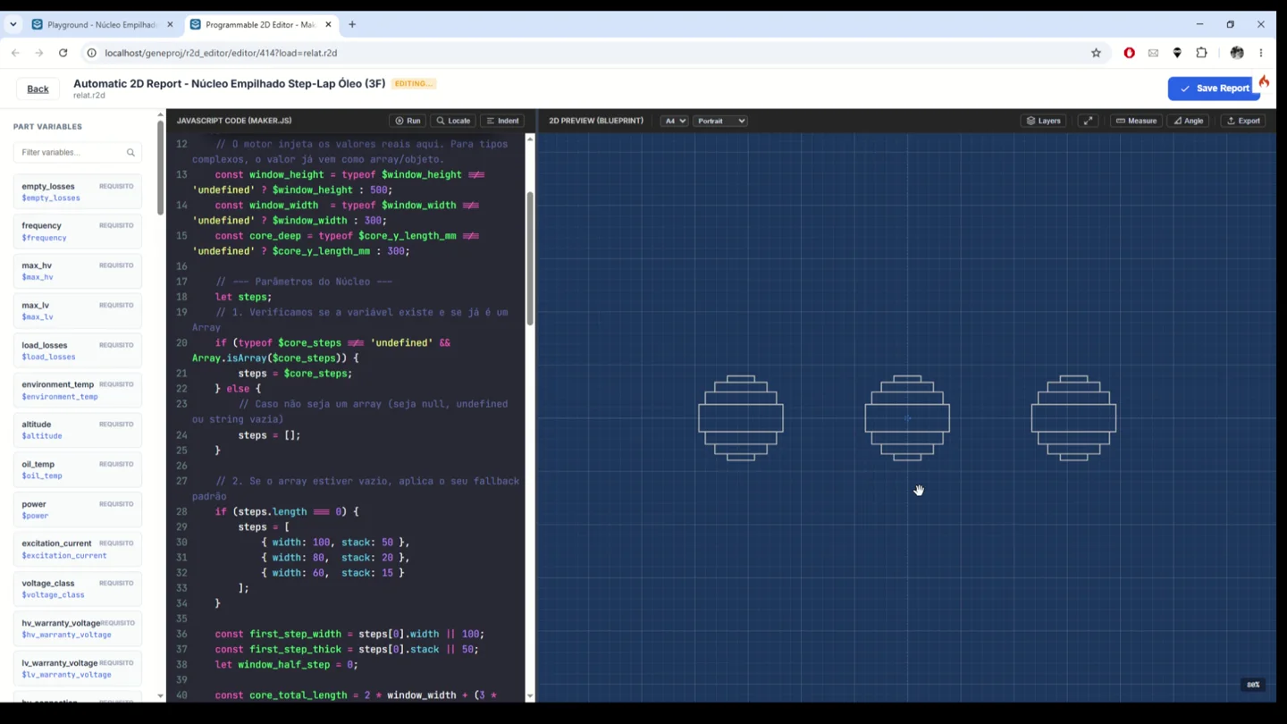
The bushing demonstration shows editable geometric elements and modeling tools in 3D CAD. The core example shows a 2D editor with part variables, drawing logic and a preview. These workflows let engineers review how the geometry and the drawing relate to the component data.
Reusable parametric parts
Build a library of parameter-driven components such as cores, windings, bushings and structural parts. A part uses its data and rules to generate the corresponding configuration, helping engineers reuse a component definition across design variations. The part workspace brings requirements, parameters, results, visualization and documents together, making established engineering work easier to apply to new projects.
- Inputs
- Dimensions and part configuration
- Outputs and application
- Reusable components across design configurations
Programmable 2D drawings
Develop 2D representations using part variables and drawing rules. The editor combines code and preview so engineers can adjust how views are constructed from technical data. In the core example, the drawing uses the information describing the core steps, providing a reusable basis for technical detailing.
- Inputs
- Variables and drawing rules
- Outputs and application
- Technical views linked to component data
Component development in 3D CAD
Work on component geometry in Geneproj's 3D CAD environment. The bushing demonstration shows the element tree, shape selection, properties and modeling tools. This environment complements parametric visualization by giving engineers a workspace to develop and inspect the geometric construction of a component.
- Inputs
- Geometry and modeling operations
- Outputs and application
- Geometric construction and component inspection
Available outputs and features depend on the configured parts, rules, permissions and templates. The engineering team reviews models and documents before use.