GENEPROJ · Engineering guides
FEM Simulator for Transformers
Use the FEM simulator to prepare finite-element studies in the project context. Organize geometry, regions, materials and scenario conditions, then review visual results from magnetic, thermal and short-circuit analyses.
Practical application
The workflow starts with setting up the simulation model and continues with reading maps for magnetic field, temperature and short-circuit forces. Results support engineering inspection and should be interpreted by the engineering team according to the study assumptions.
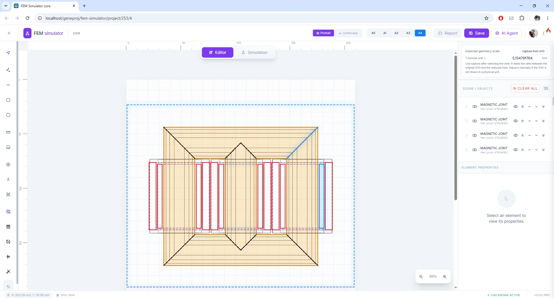
FEM simulation editor
Prepare a finite-element analysis from the project geometry. The editor organizes regions, materials, boundary conditions and excitations in the same environment used to review the components. The configuration can be reviewed before execution, keeping the study connected to the part’s engineering context.
- Inputs
- Geometry, regions, materials and boundary conditions
- Outputs and application
- A configured, traceable simulation model
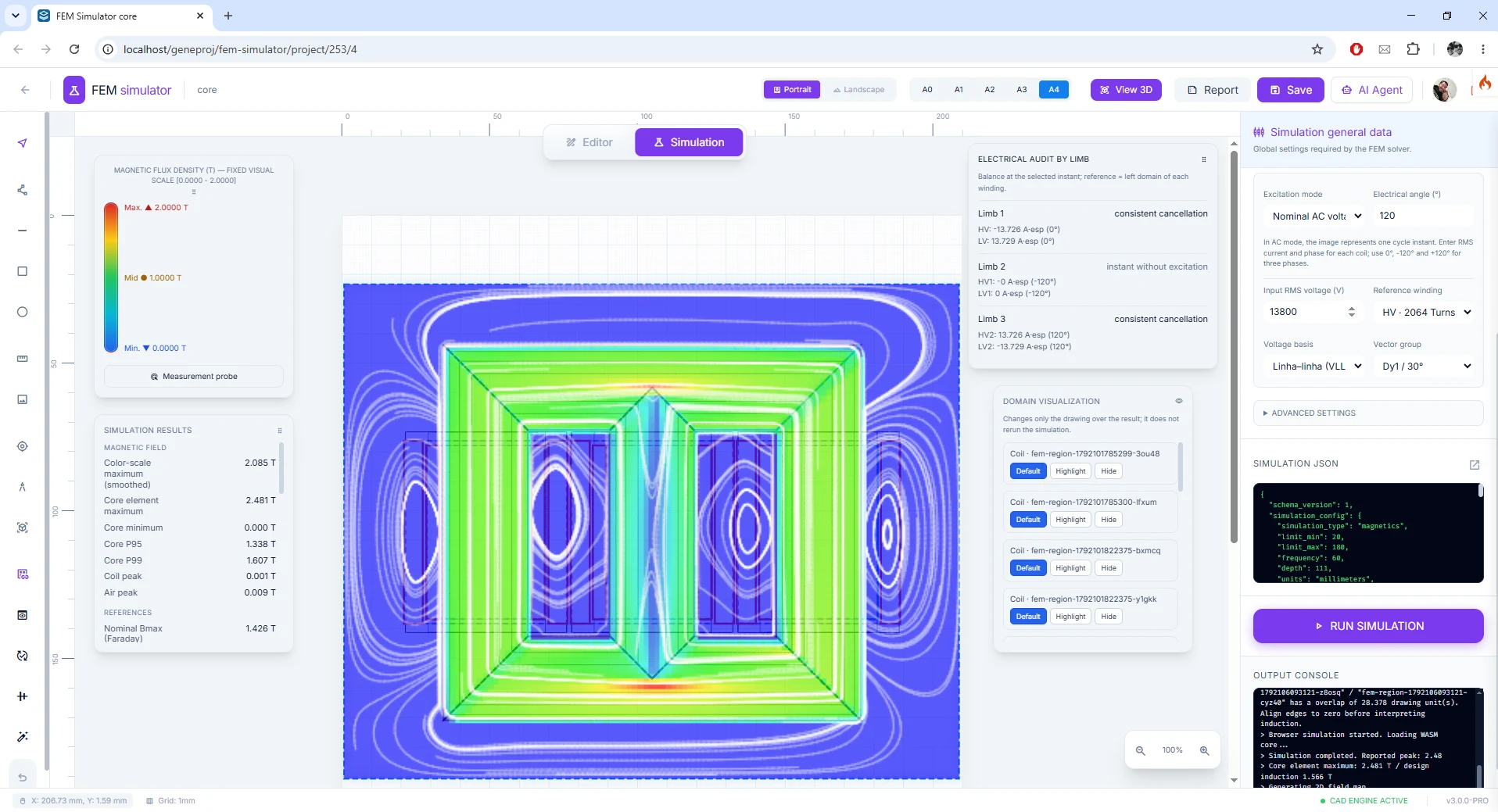
FEM magnetic analysis
Run electromagnetic studies to visualize field distribution and review quantities from the configured model. The color view helps identify highly stressed regions and compare results with the selected geometry and materials.
- Inputs
- Electrical excitations, magnetic materials and mesh
- Outputs and application
- Field distribution and electromagnetic results
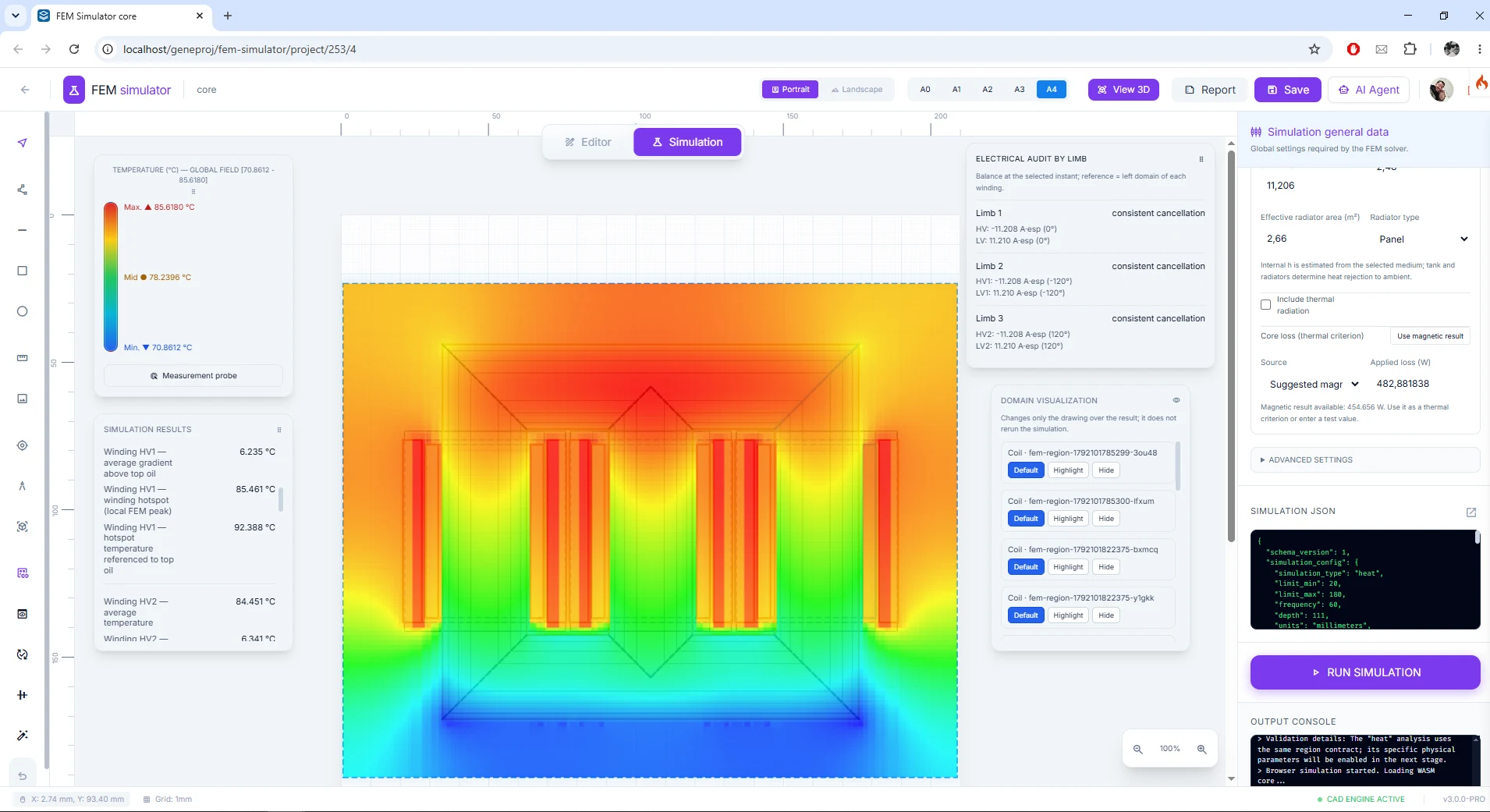
FEM thermal analysis
Evaluate thermal behavior using the conditions and heat sources defined for the study. The result makes it possible to inspect the temperature distribution and support review of critical regions in the context of the analyzed configuration.
- Inputs
- Thermal sources, materials and heat-transfer conditions
- Outputs and application
- Temperature map for engineering review
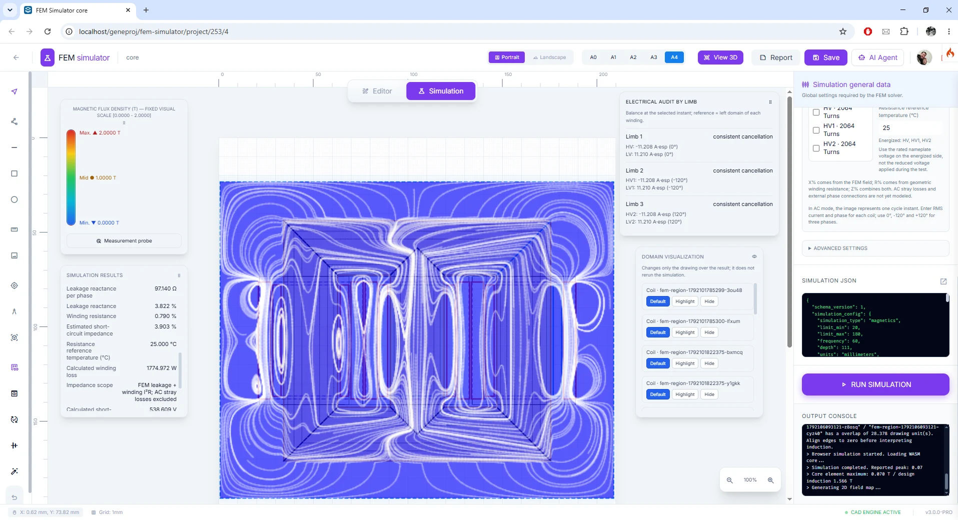
Short-circuit study
Use the simulation to examine forces associated with short-circuit conditions in the configured geometry. The study provides a visual basis for the team to compare scenario loads with the components, materials and design criteria.
- Inputs
- Currents, geometry and scenario conditions
- Outputs and application
- Force visualization for short-circuit analysis
Available outputs and features depend on the configured parts, rules, permissions and templates. The engineering team reviews models and documents before use.